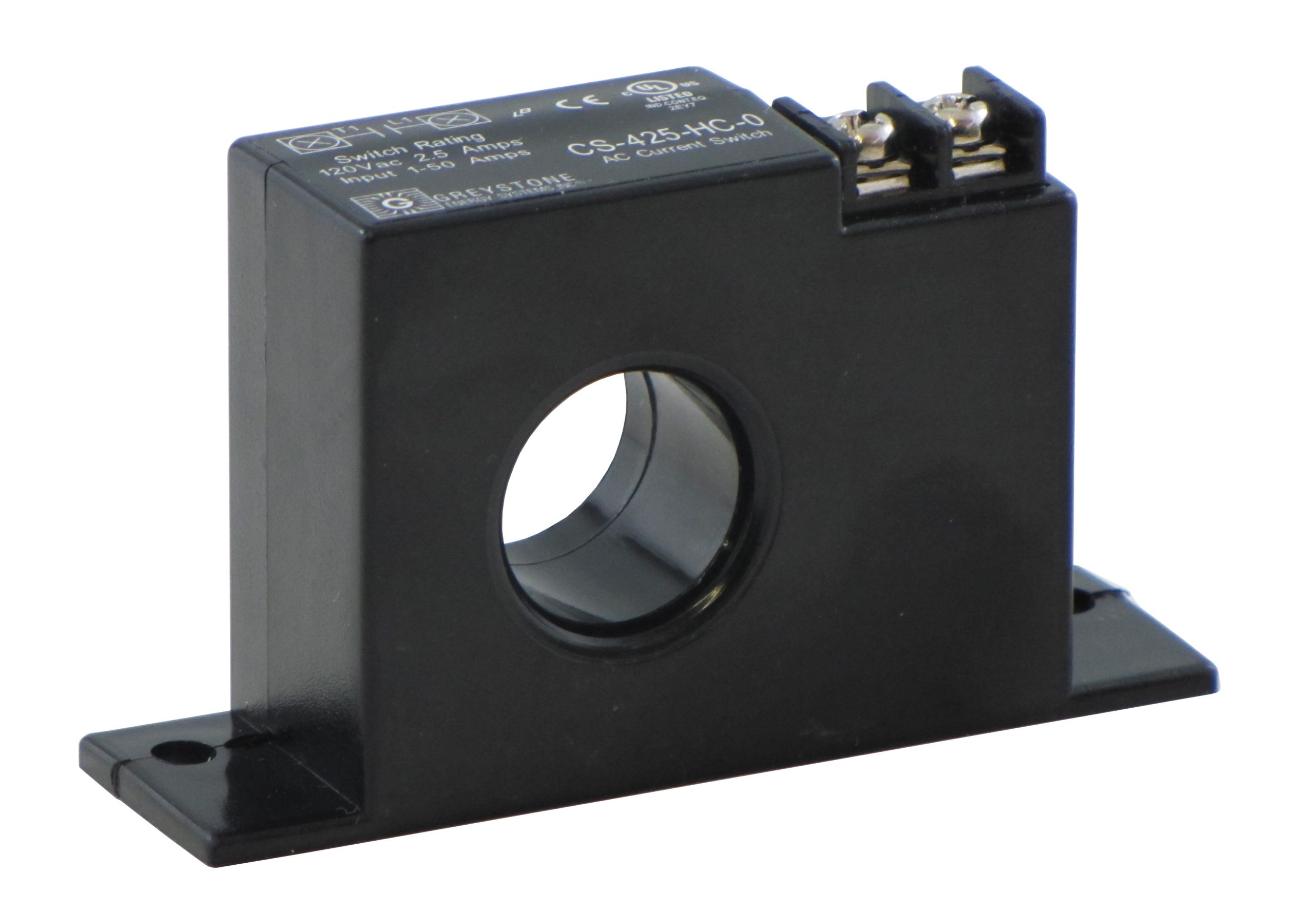
The High Current Switch / Dryer Fan Control is a solid-state N.O. high current AC switch that operates a dryer booster fan directly. This device senses when a clothes dryer is drawing ~1 Amp of current and then closes the output switch to activate the dryer vent booster fan. When the dryer cycle is complete and the current drops below the threshold, the output switch will remain closed for specified time to allow heat to be removed from the vent before the switch is opened again.
The device requires no field adjustments and only two wire connections for easy installation. It is designed to mount in a standard electrical box and the dryer supply wire passes through the center of the sensor so no physical connection is made. The device output will switch loads at 120 Vac and 2.5 Amps maximum. Internal circuits are totally powered by induction from the line being monitored and all units are cULus certified. The Triac output is a solid state electronic switch and not a mechanical relay. The Triac is almost the same as a mechanical relay, but a solid state relay does not have any mechanical parts which can wear down over a period of time. The Triac operates when it receives an electronics “gate” signal from the control circuitry, then switches to a closed or ON state thus providing an AC voltage path to activate a fan or similar device.
Specifications
| MODEL | OUTPUT | SWITCH V | SWITCH I | LEAKAGE | INPUT 1 MINUTE | INPUT 1 | TIME DELAY |
|---|---|---|---|---|---|---|---|
| CS-425-HC-0 | Triac | 120 Vac | 2.5 Amp | <1 mA | ~1 Amp | 50 Amps | None |
| CS-425-HC-5 | Triac | 120 Vac | 2.5 Amp | <1 mA | ~1 Amp | 50 Amps | 5 Minutes |
| CS-425-HC-10 | Triac | 120 Vac | 2.5 Amp | <1 mA | ~1 Amp | 50 Amps | 10 Minutes |
| CS-425-HC-15 | Triac | 120 Vac | 2.5 Amp | <1 mA | ~1 Amp | 50 Amps | 15 Minutes |
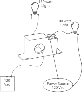
The CS-425 series cannot be tested with an ohm meter because the switch is electronic and as such will not register the same as a mechanical switch. A simple functionality test could be accomplished by using a light bulb (or floodlight which draws more amperage) to confirm device operation.
Verify that there is sufficient current to trip the current switch (minimum of 1 amp). If required the wire can be looped through twice to increase the current read sensitivity by the switch but this also divides the maximum current. For example, on the 0-50 Amp scale, if the conductor is looped through twice, the maximum current will now be 25 Amps.


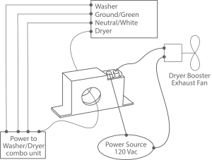
A compact stacked Washer/Dryer combo unit only has one power source cable jacket, so it can be confusing on which leg to use for this type of application. Typically the power wiring has a color code with Ground = Green, Neutral = White and two HOT legs (Black & Red) for the Dryer 220V supply. The Washer requires 120V and you need to determine if a Red/White or Black/White combination.
Turn OFF the power supply, then properly disconnect the Red leg and wire nut secure. Turn power ON and identify if the Washer can operate. If operation is normal, then use the CS-425 on the Black wire. If the operation is not normal, then use the CS-425 on the Red wire lead for monitoring “only” the Dryer amperage and controlling the booster exhaust fan. Make sure all power wires are terminated correctly for appliance operation.

